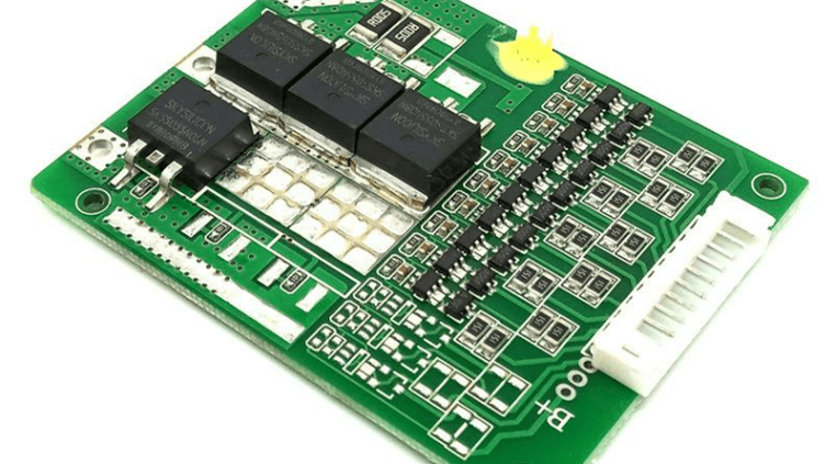
Lithium battery PCM principle
The reason why lithium batteries need protection is determined by their own characteristics. Since the material of the lithium battery itself determines that it cannot be overcharged, overdischarged, overcurrent, short circuited, and ultra-high temperature charge and discharge, the lithium battery components of the lithium battery will always appear with an exquisite protection board.
Ordinary lithium battery protection boards usually include control ICs, MOS switches, resistors, capacitors and auxiliary devices FUSE, PTC, NTC, ID, memory, etc. Among them, the control IC controls the MOS switch to turn on under all normal conditions to make the cell and the external circuit conduct, and when the cell voltage or loop current exceeds the specified value, it immediately controls the MOS switch to turn off to protect the cell’s Safety.
When the protection board is normal, Vdd is high, Vss and VM are low, DO and CO are high. When any parameter of Vdd, Vss, VM is changed, the level of DO or CO will be Changes.
1. Overcharge detection voltage: Under normal conditions, Vdd gradually rises to the voltage between VDD and VSS when the CO terminal changes from high level to low level.
2. Overcharge release voltage: In the charging state, Vdd gradually decreases to the voltage between VDD and VSS when the CO terminal changes from low level to high level.
3. Overdischarge detection voltage: Under normal conditions, Vdd gradually decreases to the voltage between VDD and VSS when the DO terminal changes from high level to low level.
4. Overdischarge release voltage: In the overdischarge state, Vdd gradually rises to the voltage between VDD and VSS when the DO terminal changes from low level to high level.
5. Overcurrent 1 detection voltage: Under normal conditions, VM gradually rises to the voltage between VM and VSS when DO changes from high level to low level.
6. Overcurrent 2 detection voltage: In the normal state, VM rises from OV to the voltage between VM and VSS when the DO terminal changes from high to low at a speed of 1ms or more and 4ms or less.
7. Load short-circuit detection voltage: Under normal conditions, VM starts from OV and rises to the voltage between VM and VSS when the DO terminal changes from high level to low level at a speed of 1μS or more and 50μS or less.
8. Charger detection voltage: In the over-discharge state, VM gradually decreases with OV to the voltage between VM and VSS when DO changes from low level to high level.
9. Current consumption during normal operation: Under normal conditions, the current (IDD) flowing through the VDD terminal is the current consumption during normal operation.
10. Over-discharge current consumption: In the discharging state, the current (IDD) flowing through the VDD terminal is the over-current discharge current consumption.


